

X6-400M XMC Module

Digital Receiver front end
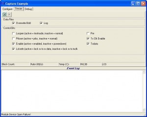
Capture Application (Windows)
Related Products
Skills Used
- Digital Signal Processing algorithms
- Microsoft C++ under Windows
- VHDL design
Outline
Entegra Solutions and Astrium have collaborated on several key engineering projects. In the example below expertise from Entegra in high speed acquisition systems using Xilinx FPGAs and Commercial of The Shelf (COTS) hardware provided by Innovative Integration are used to solve commercial engineering challenges.
It is often the case that when faced with a challenging problem the solution is not always in the internal team, rather a specialist engineering company like Entegra can be a valuable asset. Entegra has been working with Astrium for a number of years as a partner.
Experimental Radar
Astrium had been using an experimental radar system developed using a Pentland Systems Xilinx Virtex2 generation FPGA control board. Astrium needed two more systems, which unfortunately Pentland were unable to supply. The brief that came to Entegra was to engineer a solution to replace the control board that was future proof.
The existing system diagram is detailed above middle. It used 2 ADCs with an IF/4 receiver which makes the frequency down conversion easy. If the intermediate (IF) frequency is not a submultiple of the sample frequency, then the “local oscillator” in the FPGA must be able to feed all the points of a sinewave into a multiplier.
Usually the FPGA must store the points in a look up table, which consumes FPGA resources. By choosing the IF = Fs/4, the sinewave becomes 4 samples, 0, 1, 0, -1, and the cosine is 1, 0, -1, 0. This solves the problem, simply. The multiplication by the IF is followed by lowpass FIR filters and decimation. After decimation was some summing logic that summed previous pulses together, and then some application specific truncation and packeting before the data was streamed to the host board. The host board was a Kontron Pentium board.
New System Solution
Entegra’s solution was to supply the X6-400M FPGA Board from Innovative Integration with L3 ruggedisation (Military grade) and port the logic for them. Astrium were able to supply the VHDL sourcecode that Pentland wrote for them, and the software drivers for their ADC board.
The X6-400M-L3 was built to order, so there was a 12 week leadtime on the board. To reduce the risk on the project Entegra ported the logic onto a lower performance X3-10M, which Entegra had in stock. The reasons for this were:
- Using Matlab and Simulink the signal processing system could be simulated. So that it was possible to examine a set of data in the time and frequency domain to verify it was correct. Then validate the result by testing it on a running board.
- The framework logic for X3 tools supplied by Innovative were simpler to use than the Framework Logic for X6 so that the solution could be rapidly prototyped before porting to the more complex X6 which was a new COTS product at the time.
Therefore porting to X3-10M reduced the risk in several areas. The project was completed and Entegra delivered to Astrium with all design files so that they had full ownership of the solution.